Transducers installation examples
INTRODUCTION
One of the main difficulties in measuring the displacement on a circuit breaker is the position of the transducer and the attachment of the mechanical base on the breaker.
For more theoretical information on displacement tests and their interpretation, a thorough explanation may be found in the article “Displacement tests” in the Sharing Knowledge section.
CHOOSING A TRANSDUCER
In the selection of a transducer, the mechanism’s action gives a good idea of what type of transducer to choose.
If it is solely linear , as it is in the case of bulk oil breakers, or purely rotary, in the case of HPL breakers, the choice is simple.
It is sometimes possible that both types of transducers may be used, as in the case of a GL212 breaker, as shown in example 2.
In the case of the linear transducer, there is one simple rule to remember, which is to always place the transducer parallel to the breaker’s mechanism, or it could be damaged.
Finally, the length of the linear transducer used will depend on the total travel of the circuit breaker.
For rotary transducers, the following table will give the equivalent lengths, in millimeters, in relation to the number of turns.
| Transducer | ZRT-01 Single turn |
ZRT-03 3 turns |
ZRT-05 5 turns |
ZRT-10 10 turns |
| Total travel in millimeters | ± 157mm | ± 471 mm | ± 785 mm | ± 1570 mm |
NEED AND INTEREST TO MEASURE DISPLACEMENT
One question that is frequently asked is: is it necessary to measure the displacement on my breakers?
It is not always necessary to measure the displacement. It is important to check the circuit breaker’s factory manual to see if the manufacturer recommends it. The manufacturer will supply information on total travel, overtravel, displacement speed, instantaneous velocity at a given point, etc., that will be expected from your breakers. The CBA-32P circuit breaker analyzer will automatically calculate these values (see examples below).
By attaching a transducer to the contacts shows how they behave during the breaker’s movement. This information, combined with the mechanical design of the breaker, gives us valuable information on the breaker’s mechanical state, which is not always revealed in timing tests, as shown in the examples below.
EXAMPLE 1 : SHIELDED BREAKER
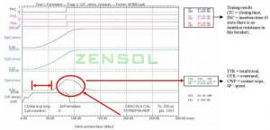
In this example, performed on a shielded breaker, three displacement transducers have been mounted, one on each phase (DpA for phase A, DpB for phase B and DpC for phase C).
Even if the contact closing time does not show any problem (the contacts are perfectly synchronized), the displacement graph shows that phase A’s travel (DpA) is not completed, which can be verified by the calculation of the total travel, which is 112 mm instead of 180 mm.
Moreover, the piston begins its movement 30 to 35 milliseconds after the main piston. The normal delay is 20 milliseconds.
EXAMPLE 2: DEAD TANK BREAKER
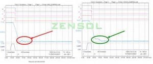
The contacts are perfectly synchronized in this example too, but the displacement curve indicates an anomalous bounce (in the left-hand graph).
The problem was due to a defective dashpot. After it was replaced, the situation returned to normal, as shown in the right-hand graph.
INSTALLING THE DISPLACEMENT KIT ON THE BREAKER
There are several types of kits available: the most used are the linear kits and the rotary kits.
These kits, even if they are called “universal”, sometimes need a few minor adaptations, as you can see in the examples below. These adaptations show the great variety of circuit breakers and mechanisms.
However, as you will see in the examples below, you will notice that there are overall resemblances between the mechanisms of certain breakers, which allow the use of the supplied kits with minimal adaptation.
Some customers which have their own machine and welding shop also develop their own mechanical bases, as shown among the photos.
MOUNTING EXAMPLES FOR MECHANICAL BASES AND THEIR TRANSDUCERS
We have gathered several mounting examples here, taken from our own test experiences over the years, in many locations around the world. These tests were all performed using the CBA-32P circuit breaker analyzer and the CBA Win software.
We hope that you will find these photos useful and that they will inspire you when you will make your tests.
We take this opportunity to thank our customers, who gave us permission to take these photos and to show them to you, so that everyone can benefit from their experience.
The examples shown below do not represent all possible cases. The displacement kits may be used for other types of breakers with either minimal adaptation or none at all.
We wish to emphasize that all the rods used to connect the transducer to the mechanisms of the breakers shown in these examples were supplied by the customer.
Practical examples
EXAMPLE 1 : ABB BREAKER
EXAMPLE 2 : AREVA GL BREAKER
EXAMPLE 3 : SPRING TYPE BREAKER
EXAMPLE 4 : T-TYPE BREAKER
EXAMPLE 5 : GE BREAKER
EXAMPLE 6 : BULK OIL BREAKER
EXAMPLE 7 : HPL BREAKER
EXAMPLE 8 : HPL T-TYPE BREAKER (BLG mechanism)
EXAMPLE 9 : GFX BREAKER
EXAMPLE 10 : GL T-TYPE BREAKER
EXAMPLE 11 : ABB BREAKER
EXAMPLE 12 : MAGNE BLAST BREAKER
EXAMPLE 13 : MOUNTING EXAMPLE WITH A MAGNETIC BASE
EXAMPLE 14 : HGF DEAD TANK BREAKER BY AREVA
EXAMPLE 15 : ABB HPL 245 BREAKER
EXAMPLE 16 : INTERRUPTOR HPL 245 DE ABB – (KIT – ZMS)
EXAMPLE 17 : WESTINGHOUSE DB BREAKER – (KIT – ZMS)
EXAMPLE 18 : DEAD TANK MITSUBISHI BREAKER – (KIT – ZLR)


